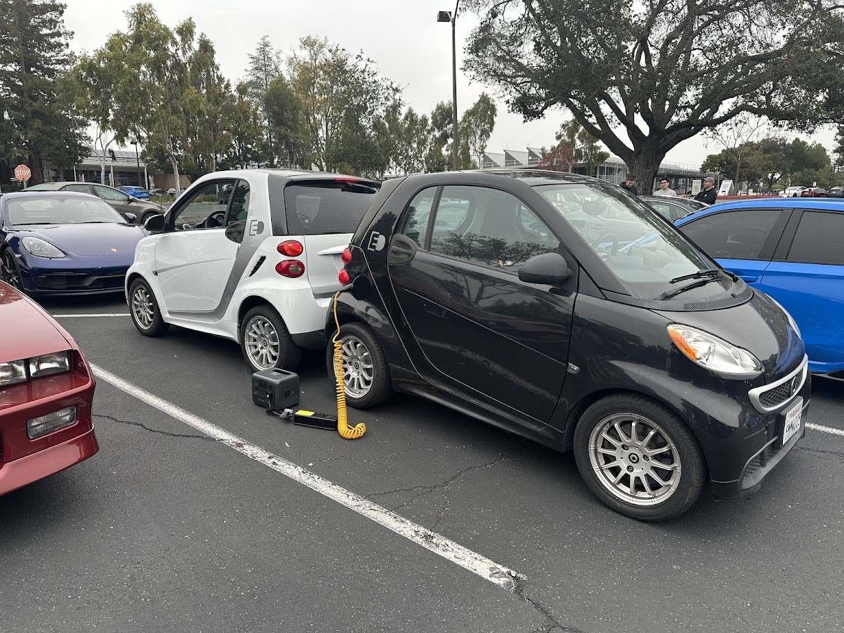
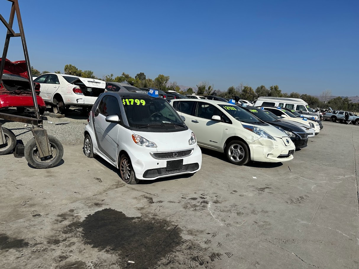
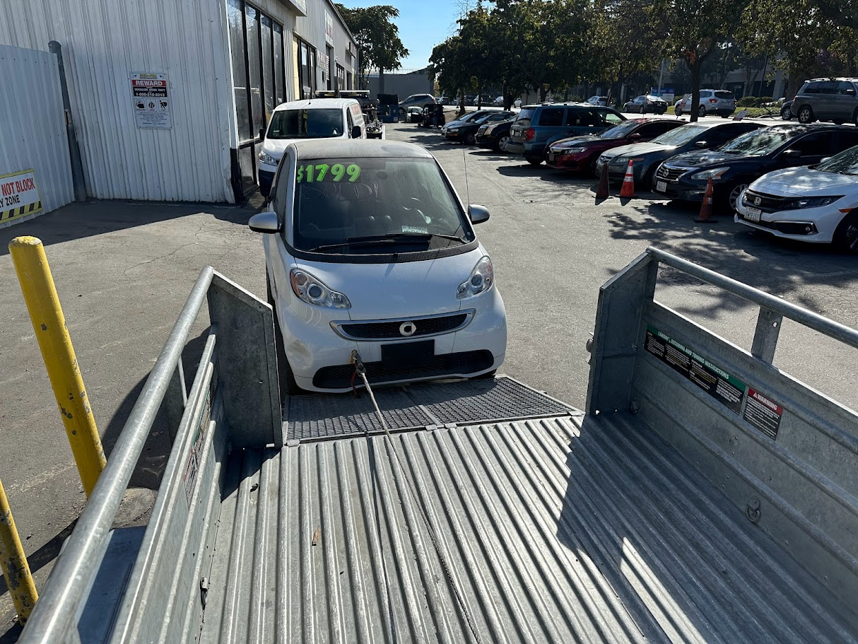
The Smart project started the way a lot of good bad ideas do: I found a very clean electric Smart at Pick-n-Pull with only about 20,000 miles on it and a completely dead battery pack. The car was a perfect little compliance-car oddball with low range, slow charging, and all the limitations people like to make fun of, which naturally made it more appealing rather than less. The real problem was that the original BMS had one especially nasty flaw: if the 12-volt battery died, the high-voltage pack could intentionally drain itself into a so-called junkyard mode, which helped make these cars effectively disposable once anything went wrong.
Rather than swap the drivetrain for something easier, the goal became keeping the car electric and building a battery pack that actually made sense. This section covers the custom replacement pack, the cooling and module mounting hardware needed to make it fit, the testing and monitoring used to validate it, and the second pack that followed once the first design proved itself.
Pack build
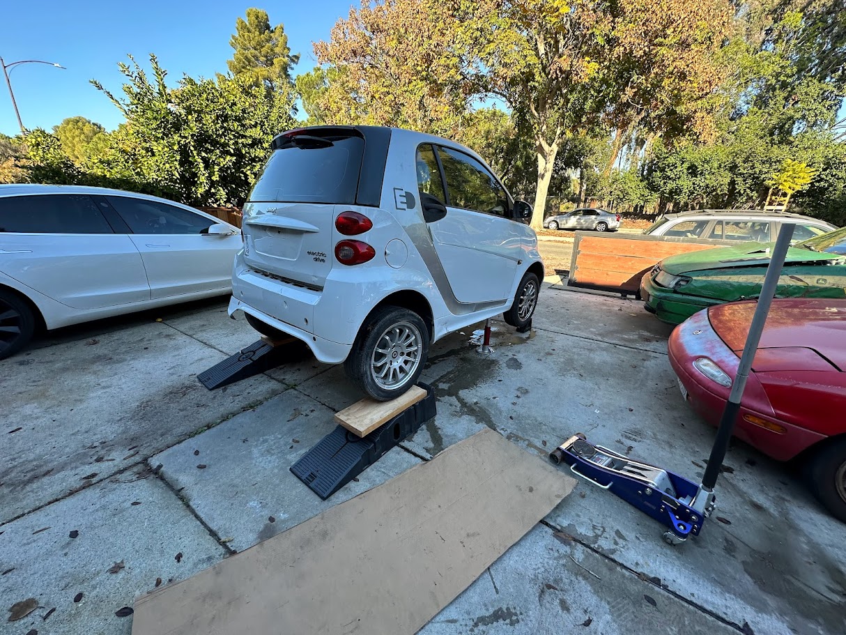
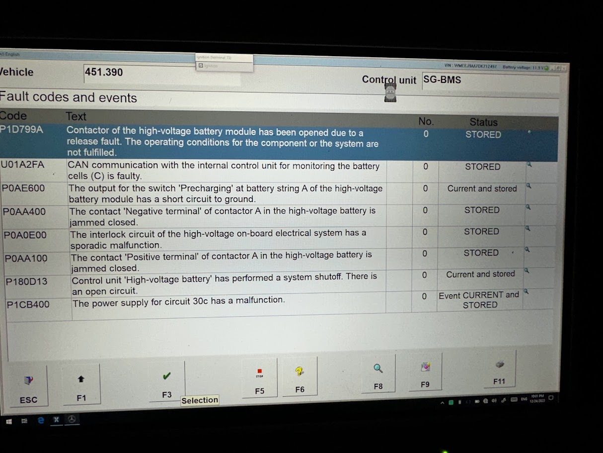
The pack build started with a battery system that was flawed in a very specific and very expensive way. On these cars, a dead 12-volt battery could trigger the BMS to put the high-voltage pack into what Daimler effectively treated as a junkyard mode, intentionally draining it down to make the car safer to salvage. In practice, that meant a small low-voltage problem could turn the entire car into scrap. When I got this one home and started digging into it, the pack was sitting at roughly 30 volts. It had not thrown the usual fully bricked codes, which at least made it interesting enough to investigate instead of immediately giving up on it.
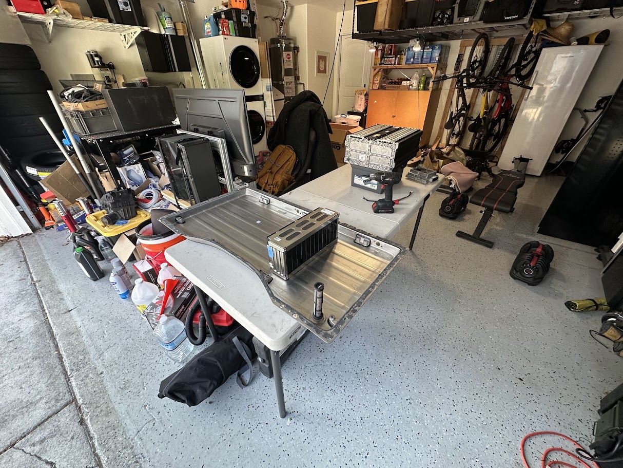
I dropped the pack, opened it up, and trickle charged the original modules one at a time with a bench supply. That did bring the cells back to life enough to prove the car out, but only in a very degraded state. Under any meaningful load the pack fell on its face, and it was obvious that the original battery was not going to be usable for long. The larger problem was that replacement packs for these cars were effectively nonexistent. Owners were getting quoted absurd numbers to replace them, even though there was basically no real inventory, no reman line, and very little meaningful support left for the platform. At that point the only sensible option was to either swap the whole drivetrain for something else or build a new battery pack. The whole point of the project was to keep the car electric, so the new-pack route won.
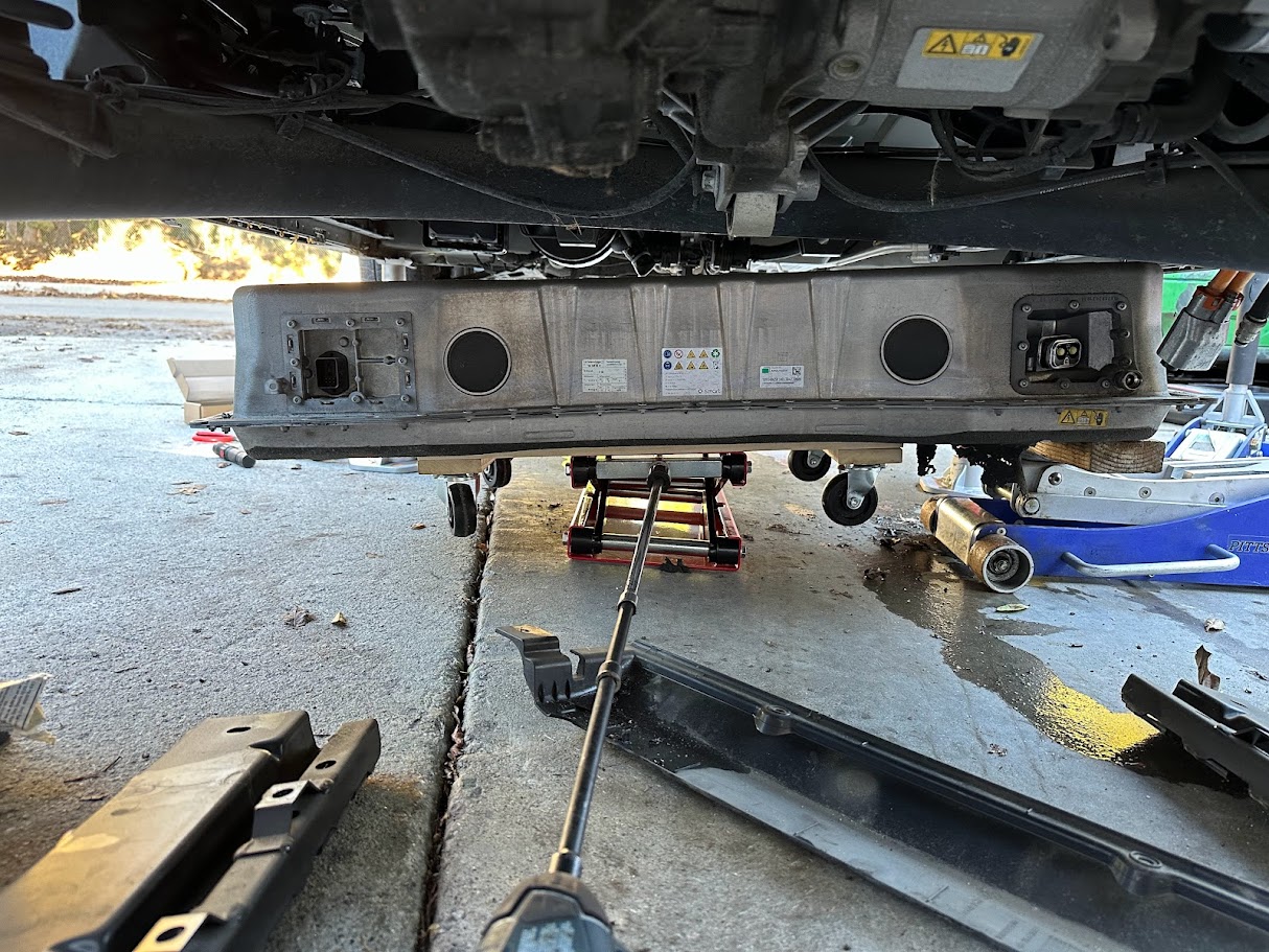
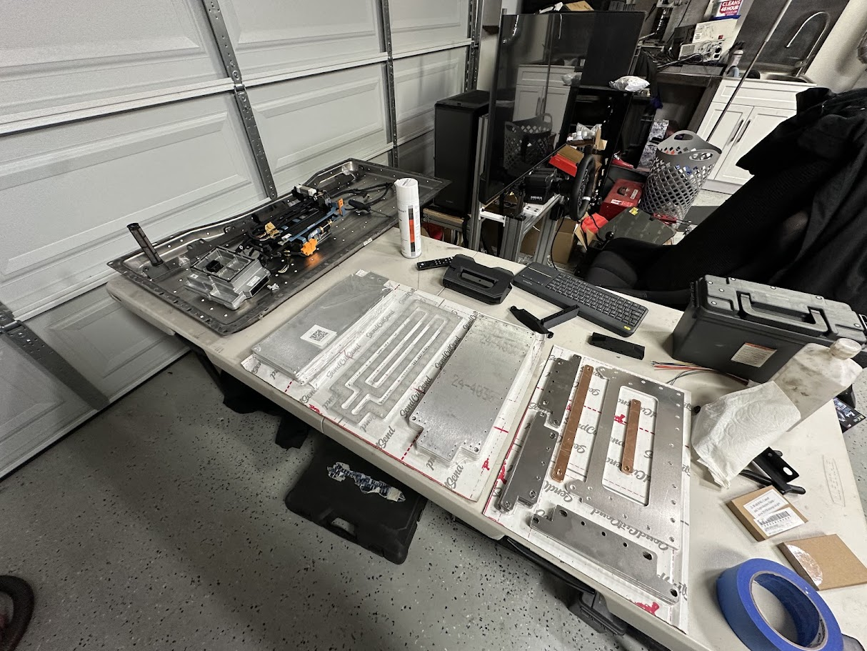
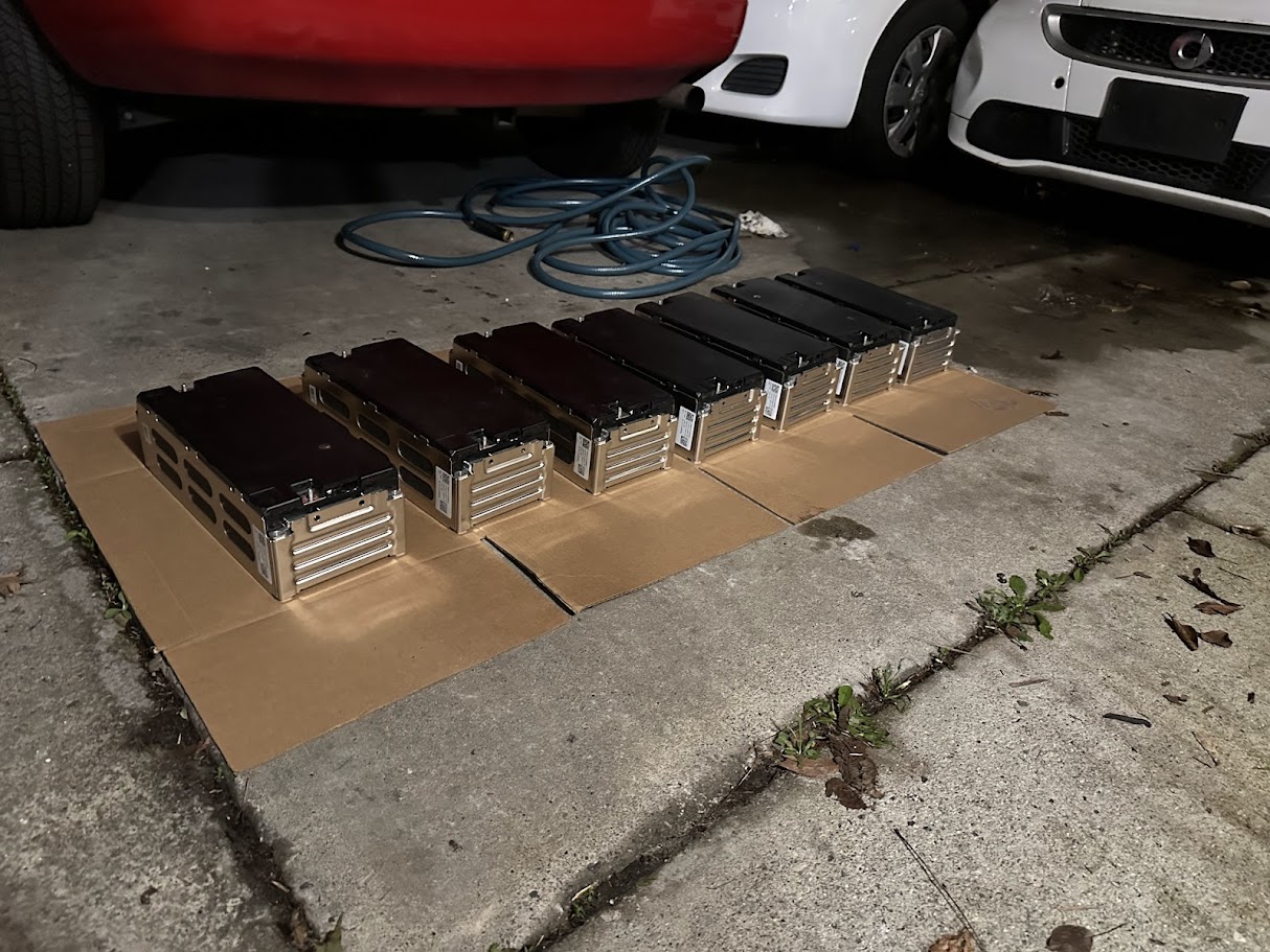
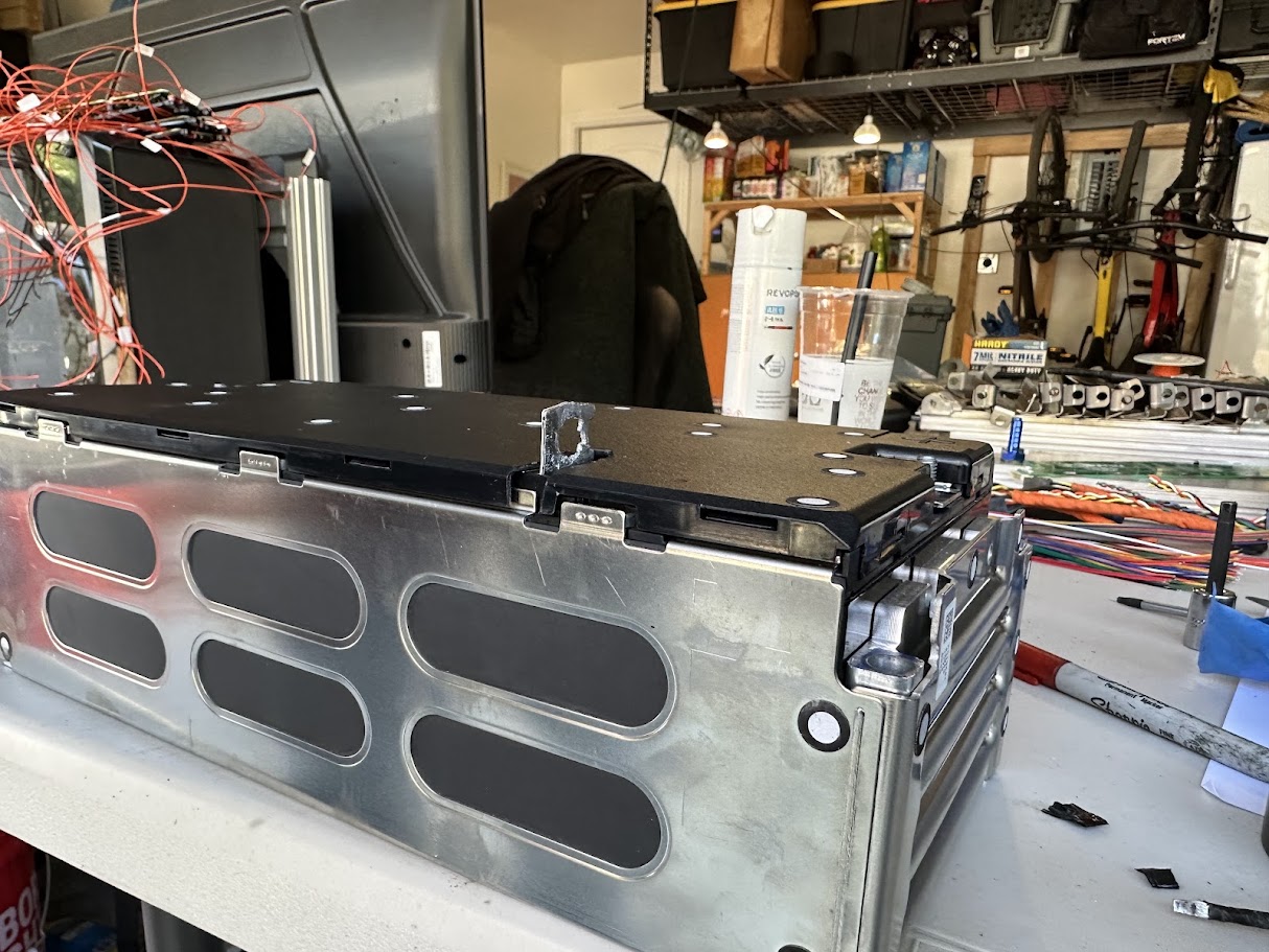
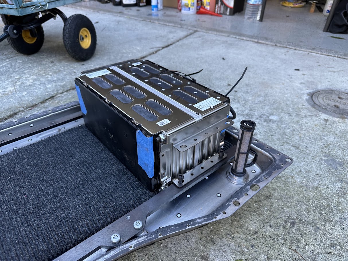
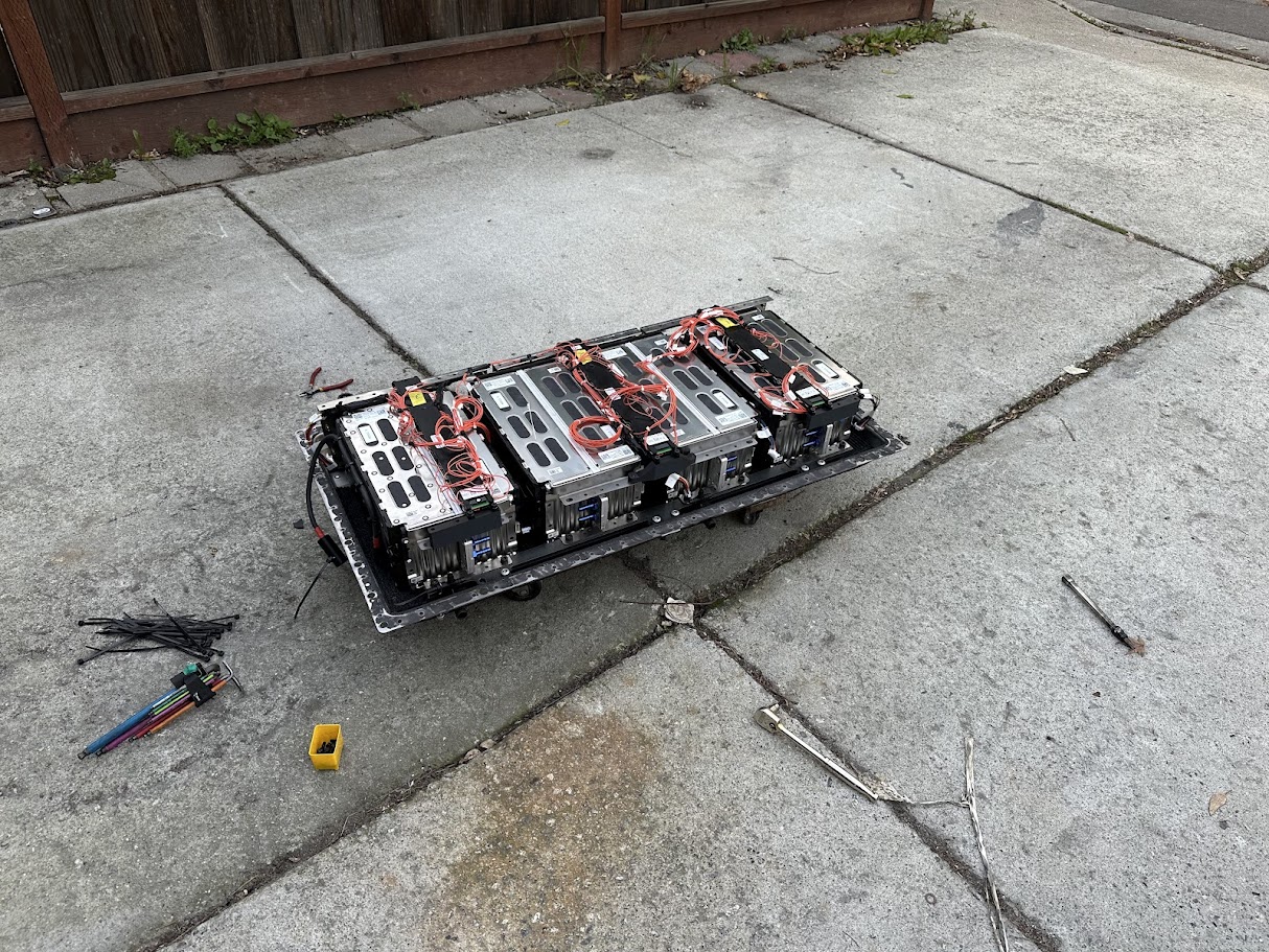
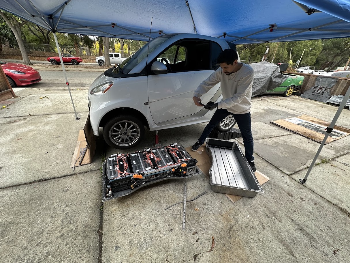
The replacement pack ended up using eight Samsung 12s modules, chosen mainly because they were readily available and landed close to the original pack capacity target of about 17 kWh. To match the Smart’s original 93-series cell count, one module had to be reconfigured to remove three cells. Before designing around the new hardware, I 3D scanned the original battery enclosure into CAD so I could work within the stock package space instead of guessing. That let me lay out the modules, cooling system, and mounting strategy in a way that still respected the original enclosure and service points.
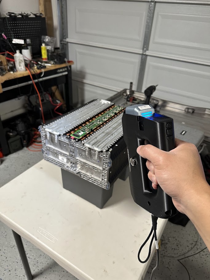
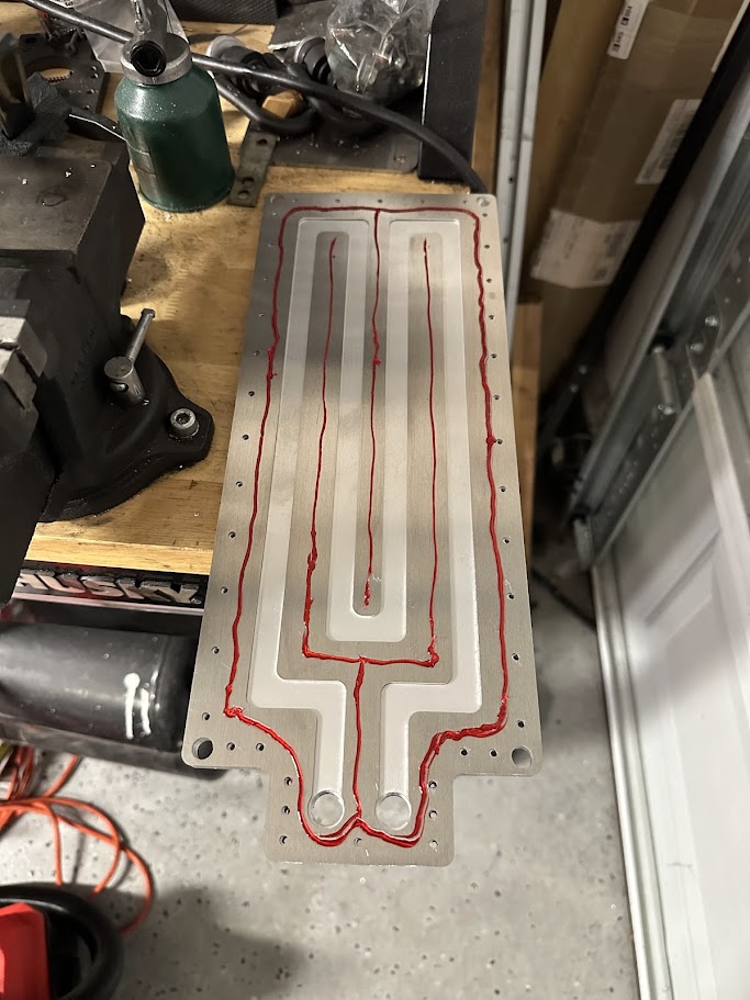
The module mounting itself was intentionally simple. I made sheet metal brackets that effectively sandwiched the modules in place, then used adapter plates to connect those new mounts back to the original module mounting points in the enclosure. The cooling plates followed the same general philosophy of making something practical and manufacturable without turning it into a science project. They were built as laser-cut sheet metal sandwiches: one flat plate, one middle plate that created the coolant flow path, and then a top cover to close the whole thing off. The layers were sealed together with anaerobic sealant for a robust, leak-free joint. Between each pair of modules and a cooling plate, I added a thermal interface material layer to improve heat transfer.
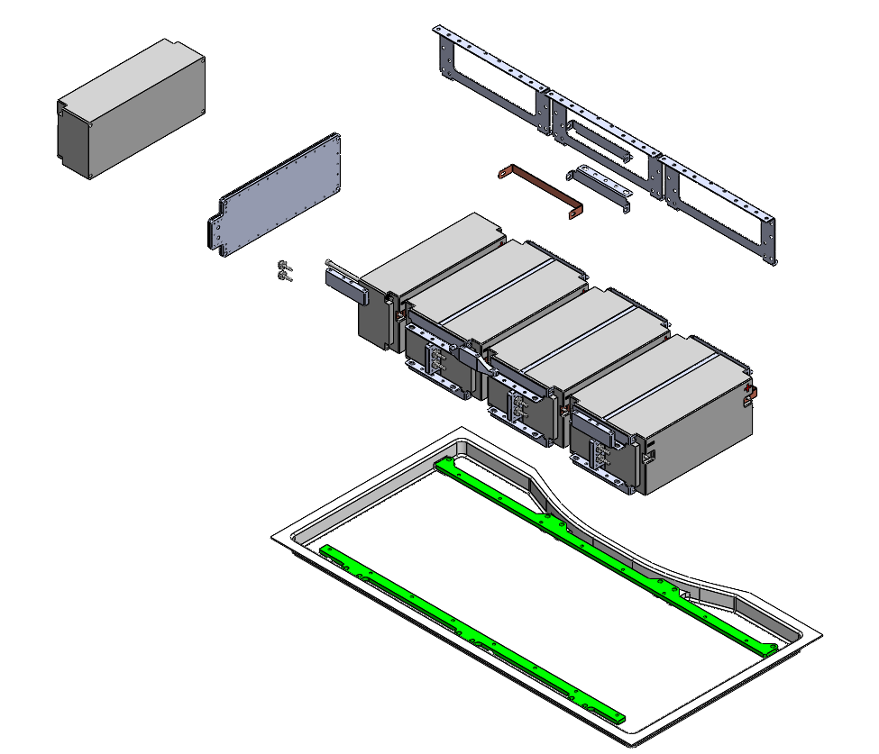
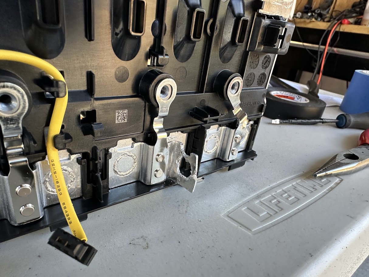
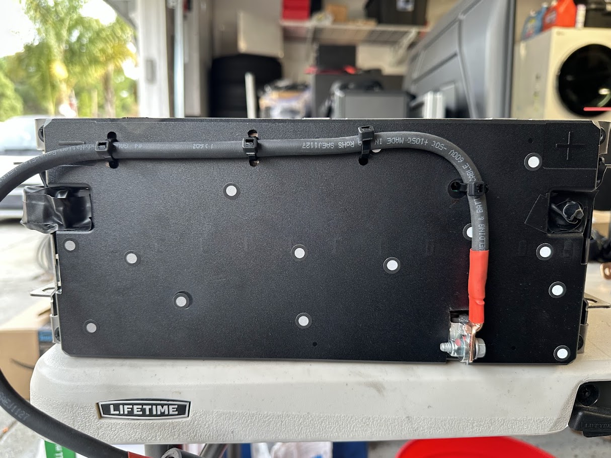
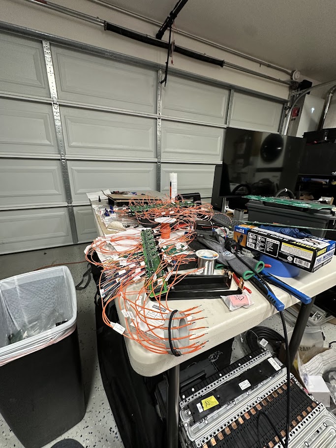
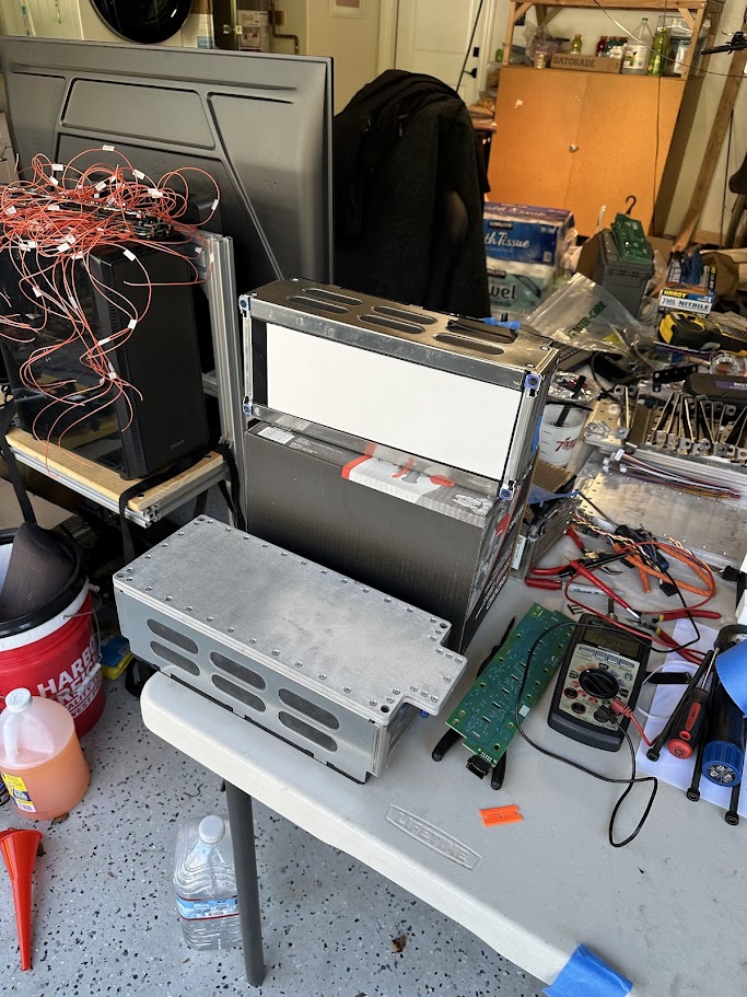
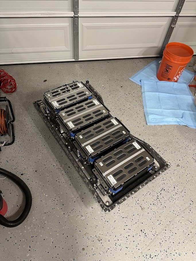
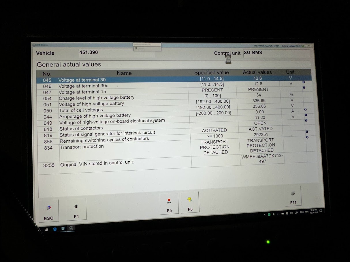
Electrically, the original BMS cell taps were rewired into the new pack so the car could still monitor the battery the way it expected to. Once everything was mounted, plumbed, and wired, I put the pack back in the car and, somewhat surprisingly, it all worked on the first try. For a project that started with a compliance car most people would have written off, that felt like a pretty good outcome. The pack build ended up folding together the original BMS flaw, the mechanical packaging, the cooling design, and the mounting hardware into one solution that finally made the car usable again.
Testing and battery monitoring display
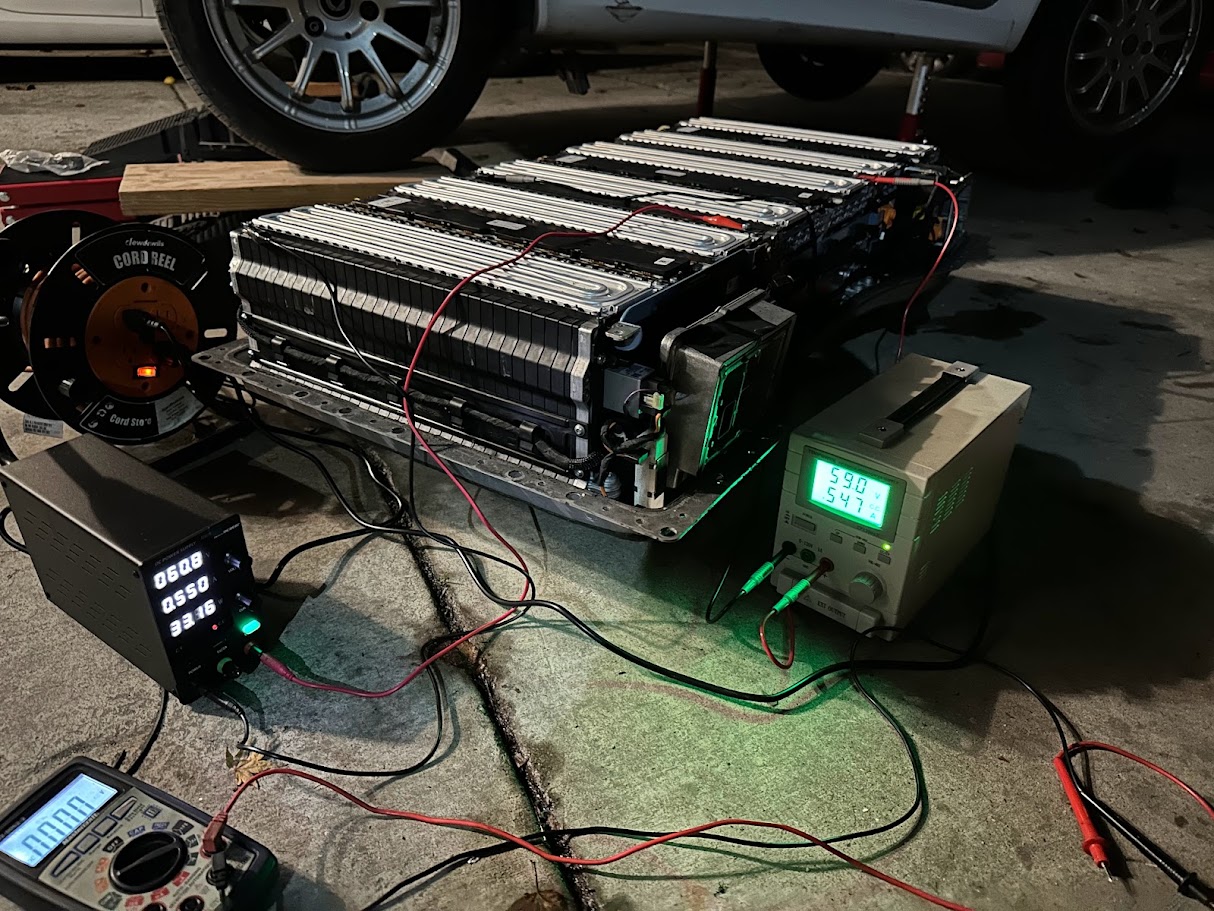
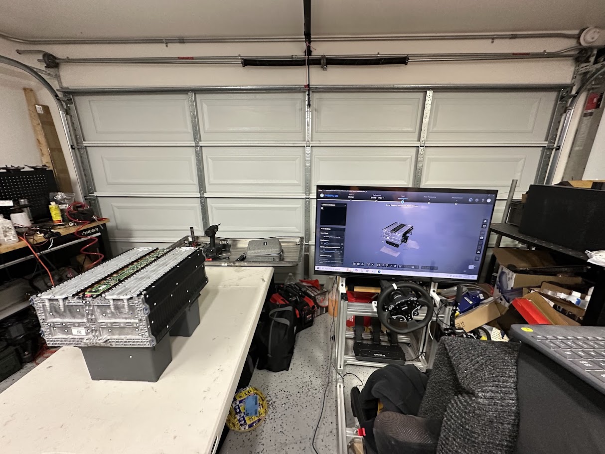
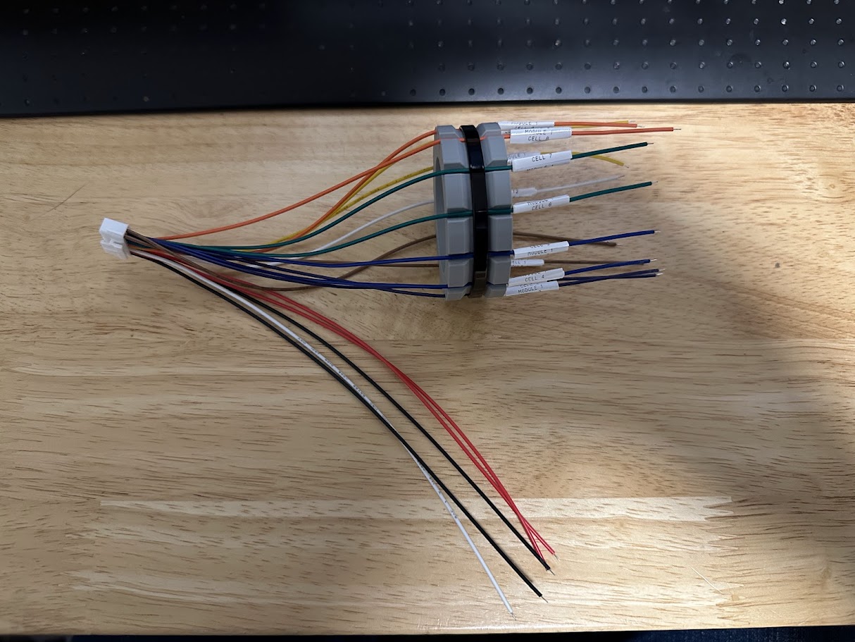
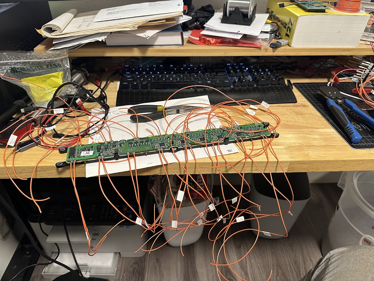
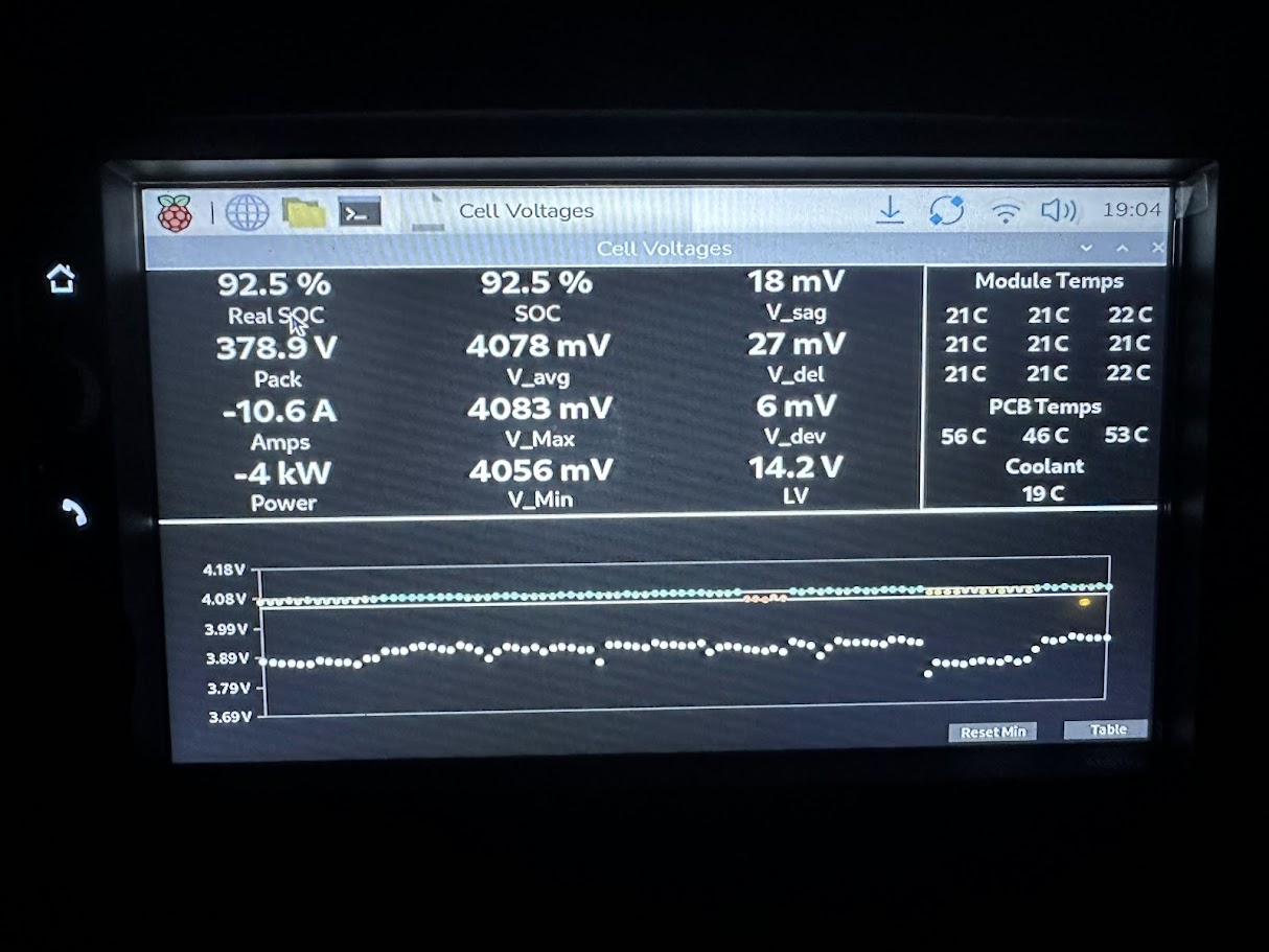
Once the first pack was built and running, the next job was figuring out whether it was actually healthy under real load instead of just technically alive. The main thing I cared about was cell voltage behavior under high current draw. A healthy module should show relatively little voltage dip, or at least a consistent voltage dip across the whole pack. To make that visible, I built a custom software tool with its own GUI so I could watch individual cell voltages in real time instead of guessing based on a few summary numbers.
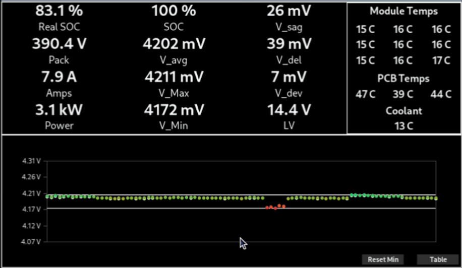
Temperature monitoring mattered just as much. The pack used nine thermistors for cell temperature sensing, along with a coolant temperature sensor and three PCB temperature sensors. That gave me enough coverage to make sure the pack was not developing a hotspot anywhere obvious and that the cooling system was doing its job. For the Samsung modules, the safe open-circuit voltage limits were roughly 3.2 to 4.2 volts per cell, so between voltage and temperature monitoring I had a pretty good view of whether the pack was behaving the way it should.
Most of the actual testing was done the simple way: driving the car around extremely hard, usually up and down mountainous terrain, and pulling a lot of continuous current in the process. Peak current was around 200 amps, which was enough to make weak modules reveal themselves fairly quickly. That testing unfortunately showed that two of the recycled modules were underperforming. One had slightly odd cell balance but still seemed usable, while another appeared to be down around 70 percent of its original capacity. That was enough to limit my real-world range to roughly 40 miles. At this point those modules are essentially known future service items, and the plan is to replace them the next time the pack comes back apart.
In hindsight, that result was not especially shocking given that these modules were presumably recycled end-of-test parts and always something of a roll of the dice. Still, the testing did exactly what it was supposed to do. It confirmed that the pack design itself worked, showed that the cooling and monitoring strategy were sound, and made it very obvious which parts of the system were limited by the quality of the modules rather than the hardware around them.
2nd pack
One of the better outcomes from the first pack build was that it proved the overall design was solid enough to repeat. After validating that the car drove well, the enclosure strategy worked, and the monitoring showed the system behaved more or less the way it should, I built a second copy of the pack to revive another dead Smart.
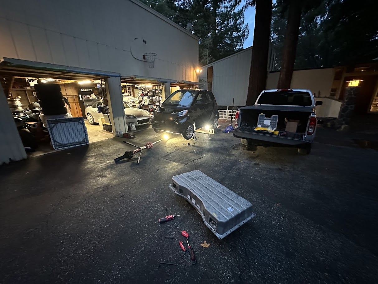
That second pack belonged to the same friend who helped convince me buying the first dead Smart was somehow a reasonable idea. In that sense, building another pack felt very on-brand. More importantly, it showed that the first car had not been rescued with a one-off lucky experiment. The design was repeatable, the packaging worked, and the same basic approach could be used to put another compliance-car orphan back on the road.
The two cars did not end up identical in outcome because module quality was still a major variable. My car ended up with about 40 miles of usable range because of two weaker modules, while Abdiel’s pack came together with healthier modules and landed closer to 70 miles. That is honestly pretty respectable for an early-2010s compliance EV. More than anything, the second pack was proof that the project had moved past being a weird battery rescue and into something that actually qualified as a working solution.